Warning: This mod has an issue with SOME devices (notably, an Amiga 500) because of the improper termination. Scroll down to the comment section for an explanation and potential workarounds. The issue is only a little noise, it’s not harmful or dangerous in any way.
This shows an RGB mod for a Philips 14GX8518. The chassis it uses is an Anubis S DD. The steps to modify it are the same for all TDA8362 based sets. I’ve also successfully modified the 25″ version of this TV (Philips Powervision family).
Theory of RGB modding via MUX
This mod was performed using the MUX method. This injects the RGB signal in the Jungle IC. Sets from the 90s to early 00s usually have RGB inputs for OSD we can abuse. They were actually used more in europe for SCART RGB and for Teletext. In markets outside Europe it’s mostly used for RGB since SCART or Teletext weren’t very popular outside europe.
The theory is explained here.
Sets after mid 2000s usually don’t have a RGB input since all of it is handled by a single uC + Jungle chip, all-in-one, and since it doesn’t need to handle RGB inputs or Teletext, it doesn’t have these inputs. Some do have a YPbPr which is almost as good, and it’s possible to convert from RGB to YPbPr with an analog converter. But this is beyond the scope of this mod.
Checking the schematics
The relevant part of the schematics are the OSD output of the uC
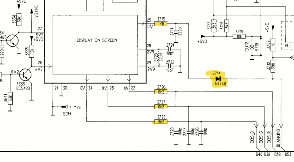
As we can see, it uses 8k2 resistors in line with the OSD, and it doesn’t use diodes. In the CRT Database table linked earlier, we can see that for this value we can use a 1032 ohm inline resistor to inject our signal. I just used 1K. Note also the 6714 diode. We can safely inject our 5V blanking signal at the cathode.
Then we need to look at the input section of the jungle IC
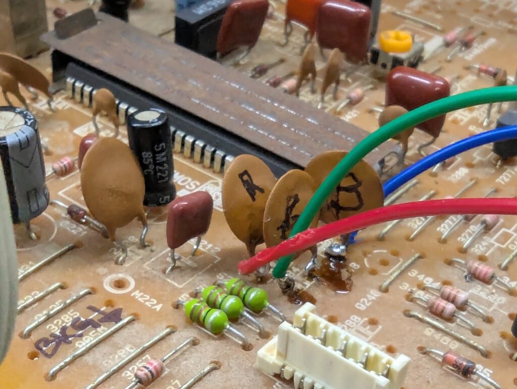
As we can see, the 2280, 2284, and 2285 caps are inline with the OSD signal from the uC and they go to pins 22-24. We should inject our signal BEFORE the capacitors. Finally, pin 21 is for blanking. Just need to inject 5V via a resistor here.
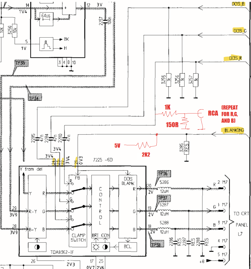
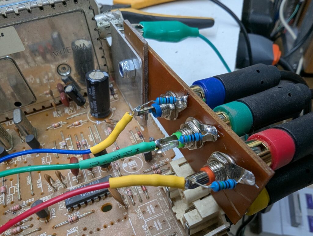
Notice I’m using a 150R terminator resistor. Usually you need 75 ohms but I found it to be too much. The image is too dark if you use 75 ohms. I was using 2×150 in parallel, so I just cut one, and it was perfect after that.
Hardware section
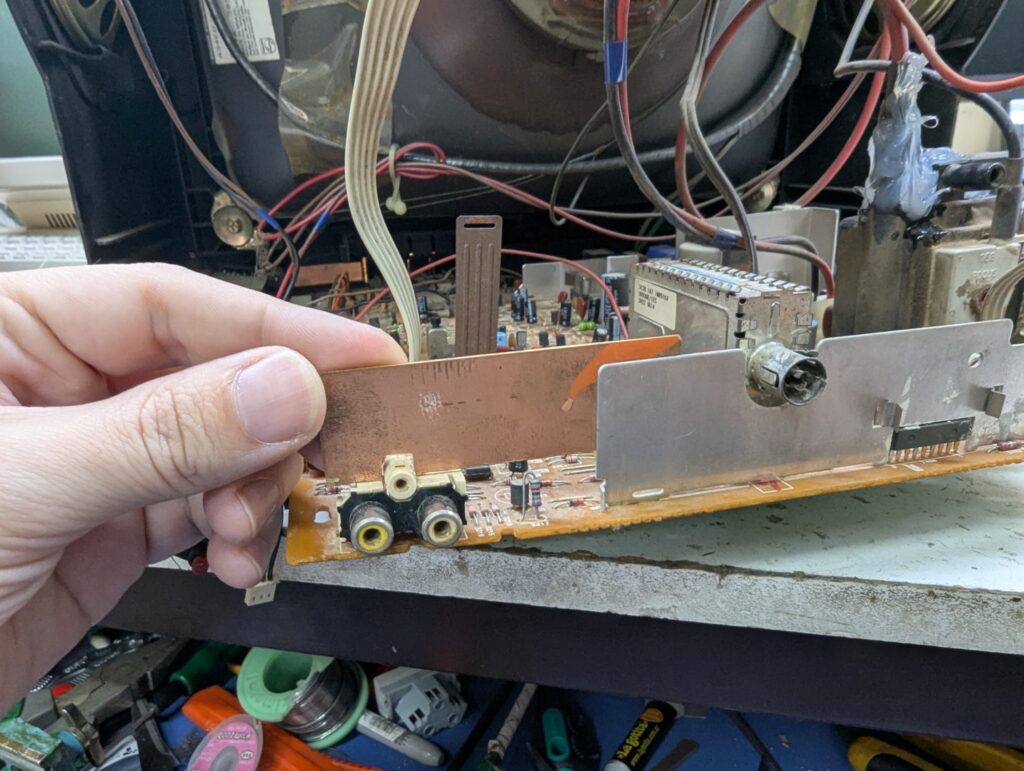
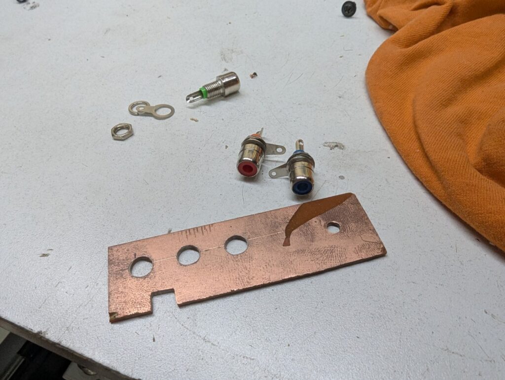
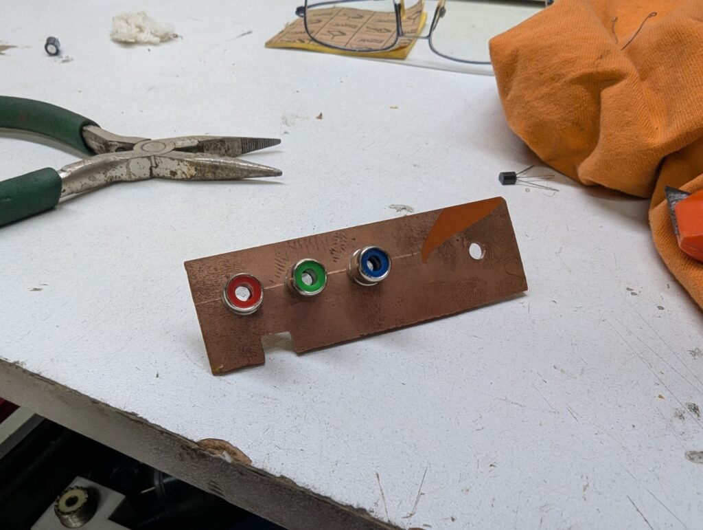
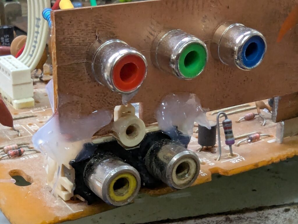
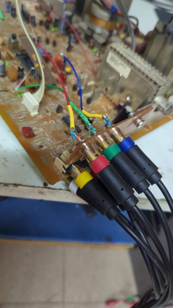
First of all we’re going to have to add the connectors for this. I like to use separate RCA connectors but you can use a SCART if you prefer. Some people also use a DB-15 VGA connector so they can use these with hacked drivers that output 15khz sync directly from a PC.
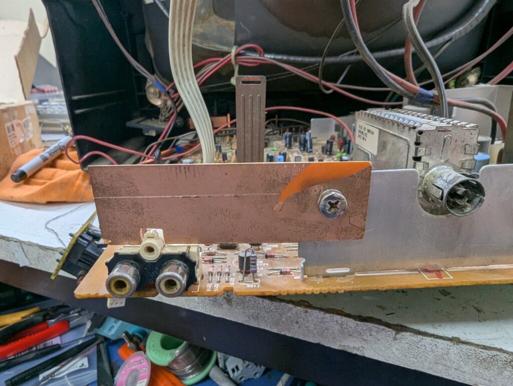
I decided to use a piece of PCB material to mount my connectors.
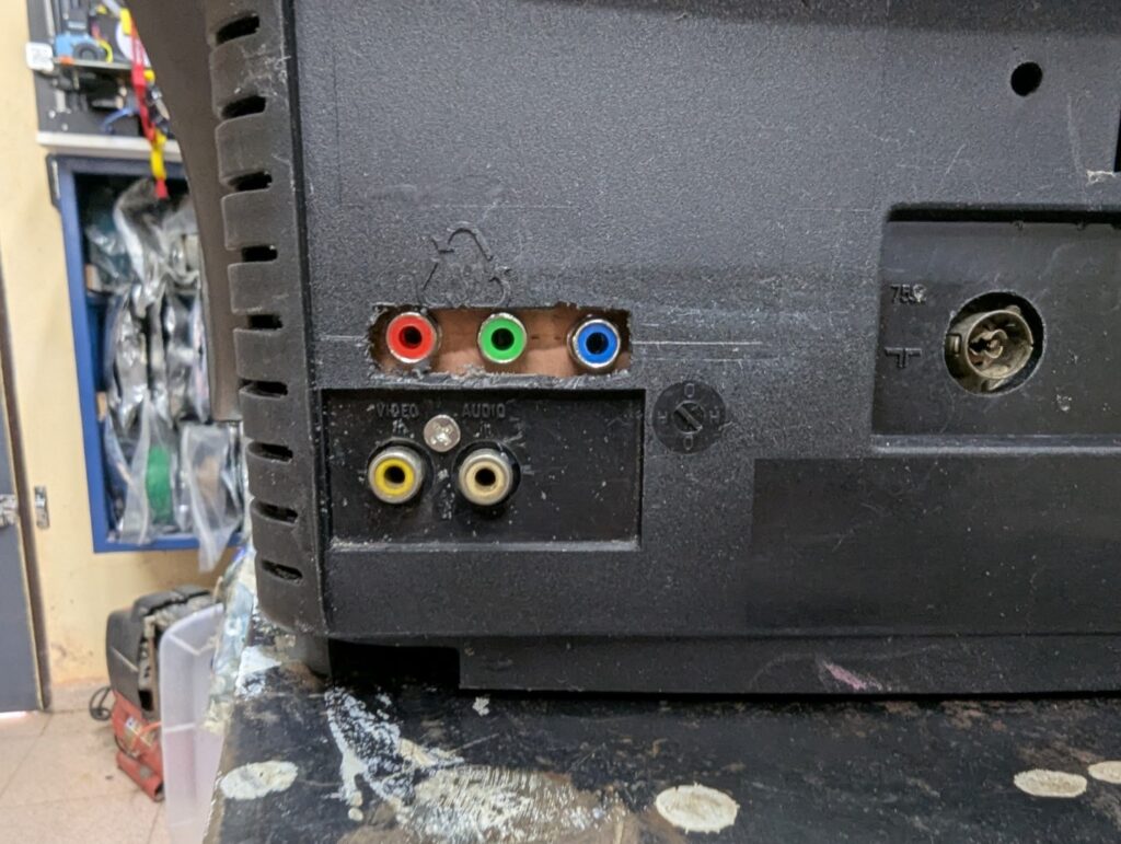
Final tests
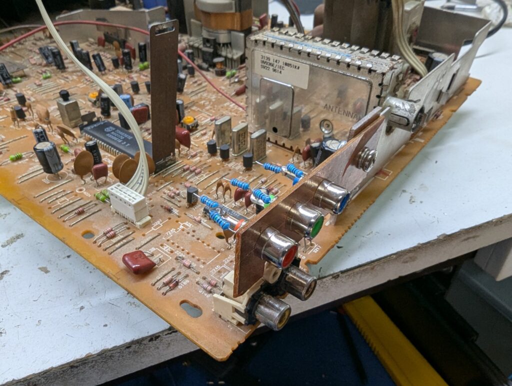
Let’s hook everything up
And turn the signal ON
It seems to work 🙂
12 replies on “RGB Mod for 90’s Philips sets”
Thanks for the guide.
Following the schematic at https://crtdatabase.com/modding/rgb-via-mux , they say to remove the factory grounding resistors (on your TV’s schematic that would be 3255, 3256, 3257). Is there any reason why you didn’t do that? I’m thinking maybe this is the reason why you had to use 150R instead of 75R for termination.
I want to follow the mod for my own Philips set with the same jungle IC, but not sure if I should remove the grounding resistors or not.
Yes, the resistors are all interconnected and interact with each other. After using this mod for a while, I found it works well in most cases but fails with the Amiga 500, where I noticed noise in the green channel. Proper 75Ω termination fixed the noise but dimmed the image overall.
The issue is that removing resistors 3255, 3256, and 3257 causes the OSD chip’s voltage to be too high. Adding diodes seemed like a solution, but routing the signal through them degraded image quality. Sending only the OSD through diodes made it disappear due to the 0.7V drop.
In short, a proper fix requires more trial and error—adjusting resistors, adding diodes, and extensive testing. For now, I lifted the OSD pins and feed the signal through 1K resistors into the existing series capacitors, terminating at 75Ω. This removes the OSD, but I can live with it until I refine the solution.
Regarding termination: video signals should ideally be 75Ω, but here they’re at 150Ω. While non-standard, it works for some consoles (e.g., SNES, N64) but not for the A500. Improper termination won’t damage the source, but it might introduce noise or artifacts.
Options:
a) Keep the mod as-is – Minimal impact, OSD works, but potential compatibility issues.
b) Lift the top side (as seen in the schematic) of capacitors 2285, 2284, and 2280 – Feed the signal with 75Ω termination and 1K series, sacrificing OSD for better compatibility.
c) A full fix – Maintain 75Ω termination, add diodes, and compensate for voltage shifts (requires more work).
Hope this helps clarify!
“Sending only the OSD through diodes made it disappear due to the 0.7V drop.”
Maybe a Schottky diode with a lower Vf would fair better?
it could be, but the OSD will still be shifted dark, the problem is that if your signal is at the normal level, OSD would be barely visible
Thank you for the info, modified my Philips 14″, it is similar to yours but with a different resistor value from OSD/MICOM, yours is 8.2K and mine is 5.6K, everything else is the same.
I studied your diagram and I think that for full MIX you need to the the following changes.
1.- Remove resistors 3255, 3256 and 3257
2.- Add a 1N4148 diode for each RGB line after the 8K2 resistor towards the jungle IC.
3.- Add a 1.6K ohms resistor for RGB inline.
4.- Use 75 ohm terminators.
Greetings!
I calculated yours by using a 0.7 PEAK value from TDA8360 data sheet.
Awesome, I’ll try this when I have some free time. Thanks for your contribution.
I just implemented on my TV and it worked perfectly, no more dark image!!
Hello, I am using your guide on a similar TV, based on the same jungle chip, can you please share where did you took 5v from? thank you in advance.
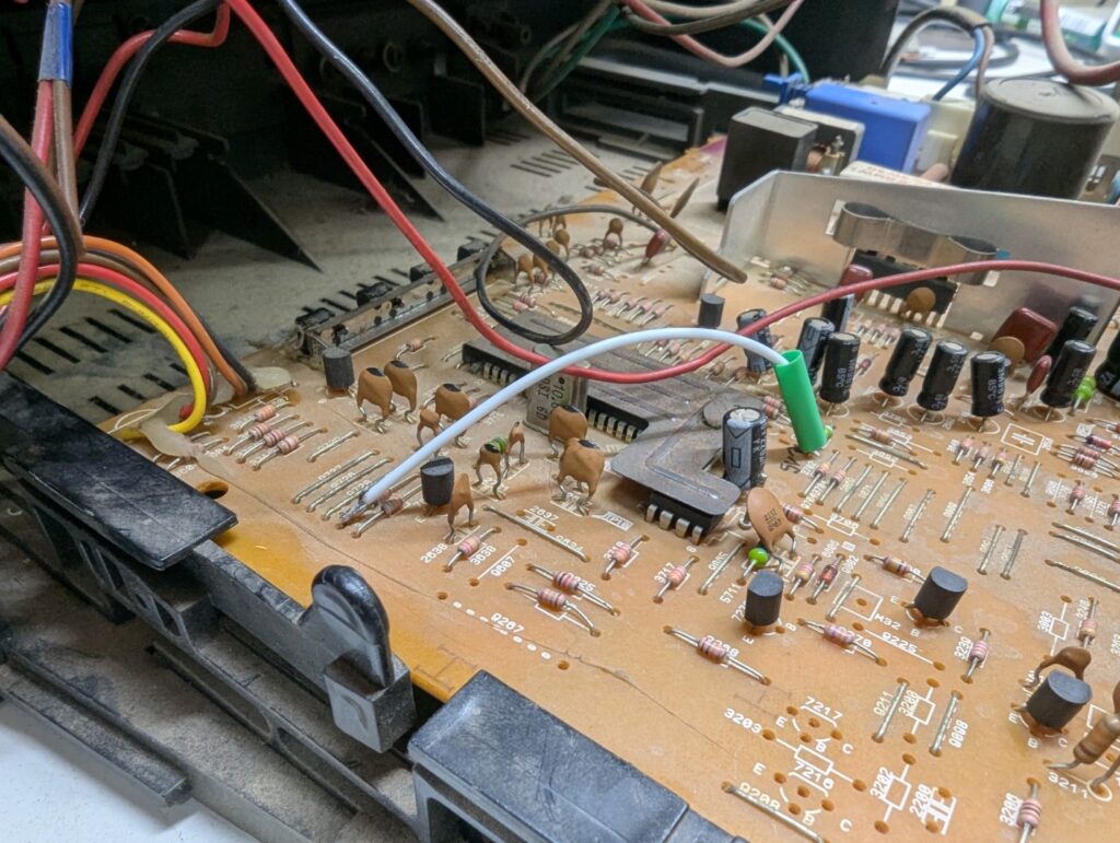
see this image: https://blog.hjf.com.ar/wp-content/uploads/2024/12/PXL_20241229_155401374.jpg there is a 1K resistor i think under the green plastic tube. the white wire is the blanking wire
Actually, I think you’ve missed something – for the stock 8k2 inline resistors, you should be using 1k3 for inline RGB! Seems like you took the values for 6k8 from the table
[…] few months ago when modding my CRT I learned, thanks to this reddit thread, about the G1 mod. G1 is one of the terminals that control […]