Many years ago I bought a uIEC 3.2 from go4retro.com. The website mentioned that there is room in the PCB for a DS1307Z RTC, so I wanted to see what it was about. This was a long journey until I was finally able to make this work.
Part 1: The hardware
This part is easy enough. We just need the DS1307Z and its supporting components: two resistors, two capacitors, and a crystal.
The easiest and cheapest way to get all of this is to buy one of these cheap “Arduino” modules that will have all that’s required. I got this one for $1.
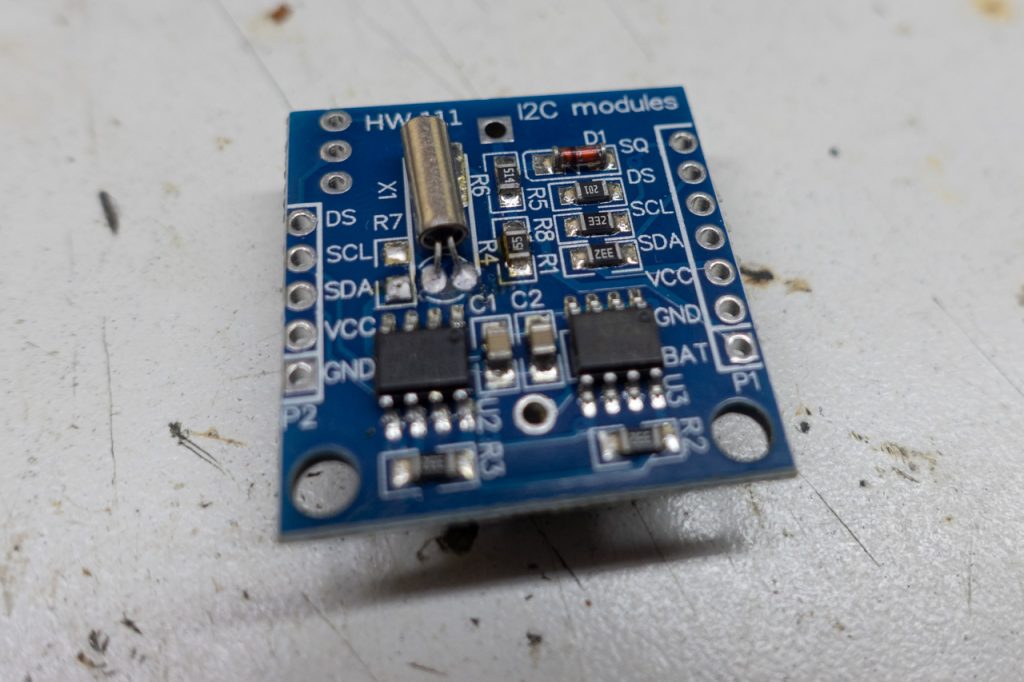
All we need to do is to transplant the components from one board to another. The uIEC board is unmarked so we need to pay attention to the orientation of the IC. It’s easy enough, since pins 1 and 2 of the IC go straight to the crystal. We just need to make sure the dot in the IC is on the crystal side:
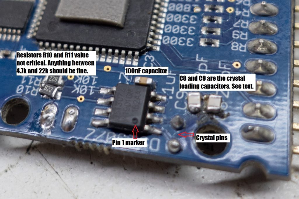
Then you need to solder the crystal and its two capacitors, and the pull-up resistors for I2C.
Finally, you need to add a CR2032 or similar battery. You can use the holder that comes with the donor module, but it may be a better idea to get one of those batteries with leads, like this:
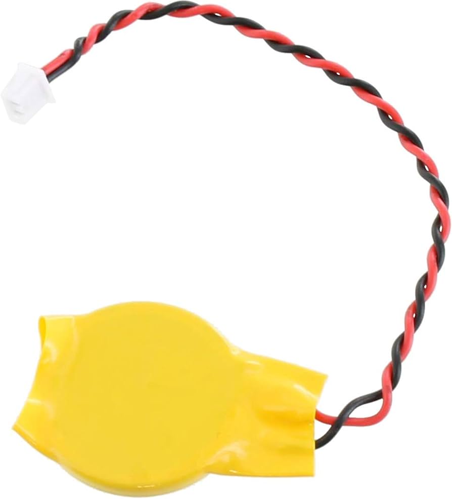
I just stuck the holder on top of the microcontroller with some double sided tape, and soldered it to the PCB.
About the loading capacitors
All crystals need a loading capacitance to work properly. This is specified in the crystal’s datasheet but we’re using generic components. We can only guess what the required load is. But it’s usually between 10-25pF.
PCB layout is also important. The PCB traces have some capacitance, which we can’t really know. May be insignificant, may be a couple pF, so whatever capacitor we put in there will be added to this capacitance.
In short, the reality is that you need to try it until it works. I was using the caps included in the donor board, but this just didn’t work. It started working when I removed the capacitors, but the clock was running slow. I soldered in a couple of 9pF capacitors, and it improved significantly, but it was still slow. I need to replace them until i found the required ones for this circuit.
You can’t really measure the frequency of the running crystal as the oscilloscope will introduce a significant capacitance (usually 6pF). In x10 mode this is reduced, but you’re still having a probe effect.
You can, however, enable the clock output in DS1307Z and measure that. This is out of the scope of this post. I may update this in the future.
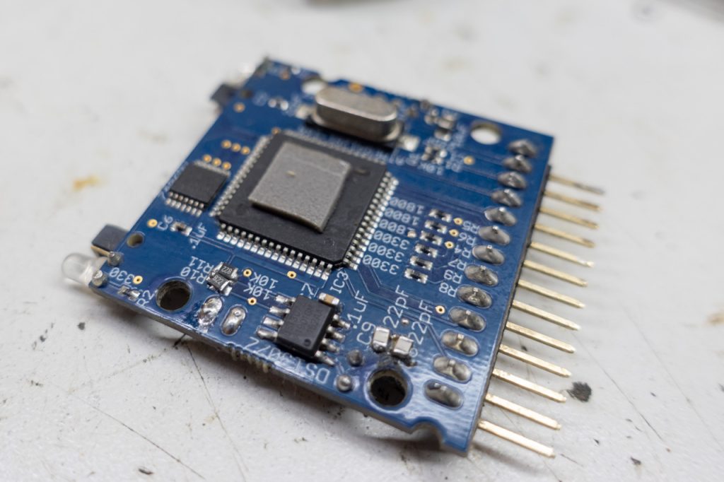
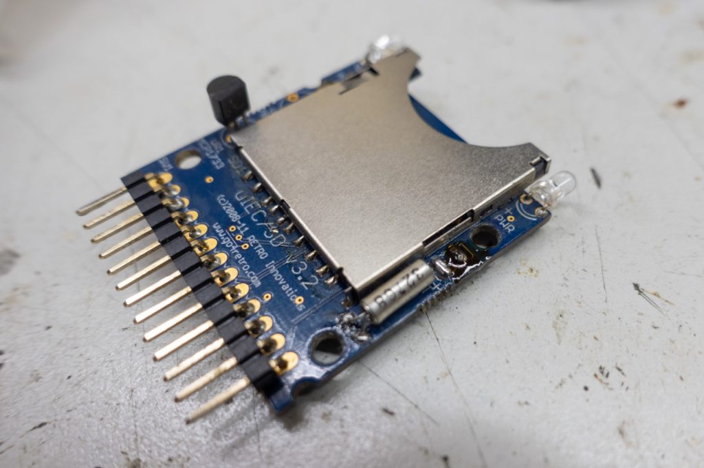
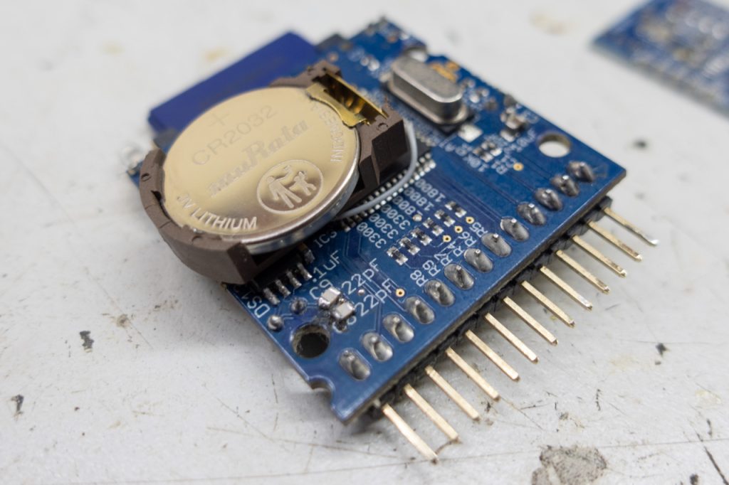
Anyways, when you’re done, this is how it’ll end up looking:
Part 2: The firmware
tl;dr: use my fork or the prebuilt binary.
Getting it to compile
This was the difficult part. Boy this took me a while to figure out. I connected the device, but it simply didn’t work. So I looked at the source. The docs said this needs version 1.6.x of avr-libc to build. So I tried to build and it failed.
I installed an ancient version of Debian in a VM but it also failed. I made it compile by removing -Werror from the Makefile.
But when I enabled DSRTC I had a ton of errors again. They were related to the I2C bus. So in the end, nothing of this was necessary. It compiles just fine in a modern system.
Setting up the build environment on Linux
If on Debian or Ubuntu, just:
apt install -y build-essential gcc-avr avr-libcthen clone the repo:
git clone https://github.com/hjf/sd2iec.gitand finally cd into the directory, and run make
My fork contains all you need to generate a binary. After this, take the sd2iec.bin file and copy it in your SD card. You should see the green LED blinking a lot. This means it’s updating its firmware. After it’s done we’re ready to use it.
Part 3: Using it
So in order to use this, you need to issue some commands. These are compatible with ancient CMD drive commands. The FD2000 drive, for example, included an optional RTC that operated just like this one.
The easiest way to use it is with JiffyDOS. Otherwse you’ll need to issue the commands with OPEN and read back the drive’s error channel. Not fun.
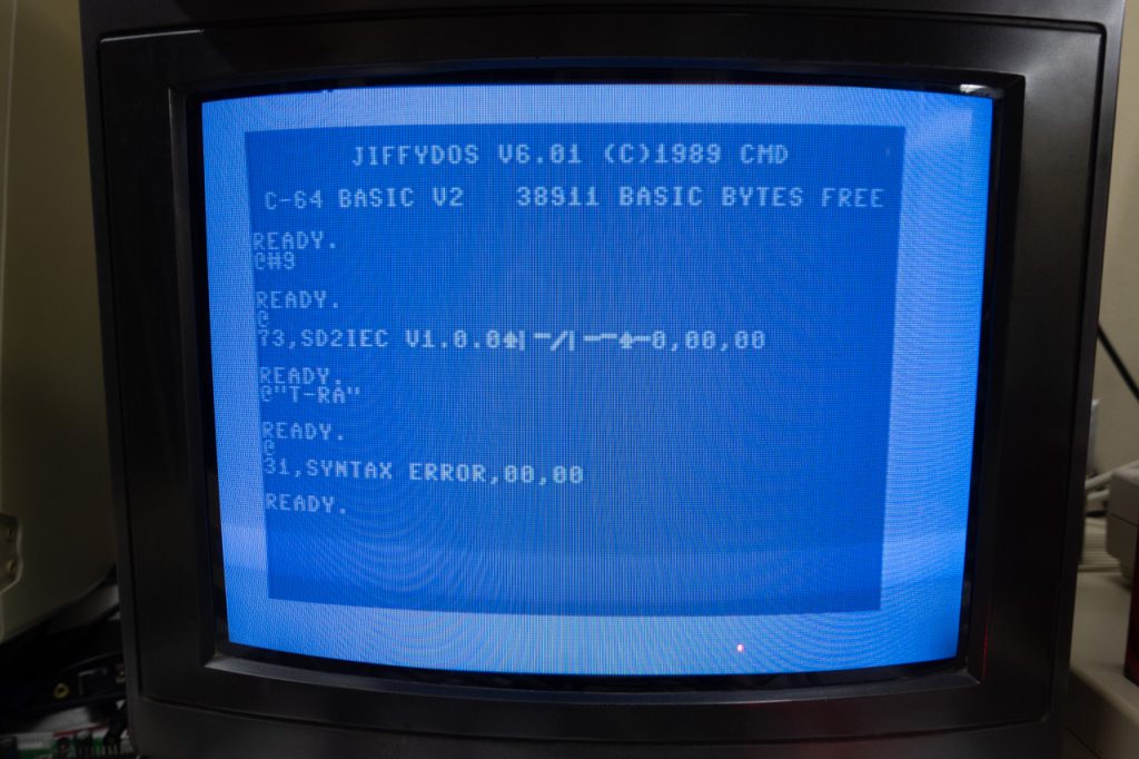
So armed with JiffyDOS we do simply a @ to test communication. We should see:
73,SD2IEC V1.0.0...,0,00,00
Then we can try @"T-RA" (Time – Read Ascii)
it’ll respond with
31,SYNTAX ERROR,00,00
this means the clock isn’t set. So we set it with
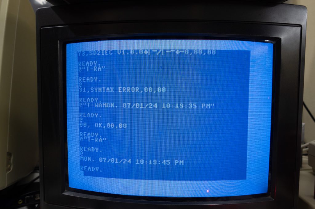
@"T-WADAY. MM/DD/YY HH:MM:SS AM"
for example:
@"T-WAMON. 07/01/24 12:00:00 AM"
After this we can issue an @ and we should get:
00, OK,00,00
Finally we can do @T-RA and we should get:
MON. 07/01/24 12:00:05 AM
if you’re getting the same time you entered (time isn’t advancing), this mean the oscillator for the RTC isn’t working. You need to check your connections and if everything is OK, you may need to change the crystal’s capacitors.
Now try turning your Commodore off for a few seconds, and on powerup it should respond to @T-RA with the right date and time. This means the backup battery is working. If it responds with SYNTAX ERROR, this means your battery isn’t connected properly (because you connected a battery, right?)
On the subject of capacitors, remember to check for drift. Wait several hours and make sure the RTC isn’t running too fast or too slow. If it’s drifting too much, it means your loading capacitors aren’t the proper value. You’ll need to experiment with different values. Maybe even replace it for a good japanese crystal and proper X7R capacitors.
Usage with GEOS
The RTC is used automatically by SD2IEC to keep track of file timestamps. If you create new files they will have the right date and time.
But a more practical application is GEOS. It has a real time clock, so why not use SD2IEC to set its time?
There is a very old application called CMDTime. This was used to set the time from CMD devices such as the FD2000. It automatically runs on boot, and will set the proper date and time.
Here’s a D81 file ideal for use with uIEC. It contains GEOS and a bunch of apps, and I’ve copied CMDTime into it:
I got this from the ultimate GEOS resource, https://www.lyonlabs.org/commodore/onrequest/geos/index.html and reuploaded it here with permission.
It needs to run off drive 9, so you can:
OPEN1,9,15,"U0>"+CHR$(9):CLOSE1
OPEN1,8,15,"XW":CLOSE1
to change it. Avoid XW if you don’t want to make this change permanent, or change CHR$(9) to CHR$(8) to revert.
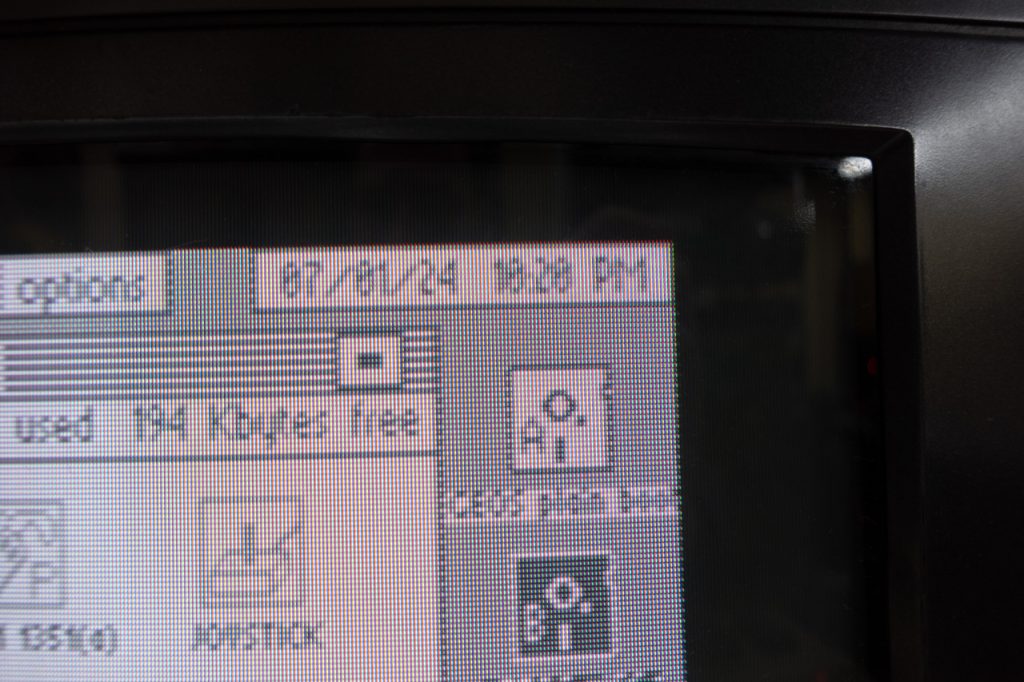
Once it’s ready, just do SHIFT-RUN/STOP to start up GEOS. After it loads you should see:
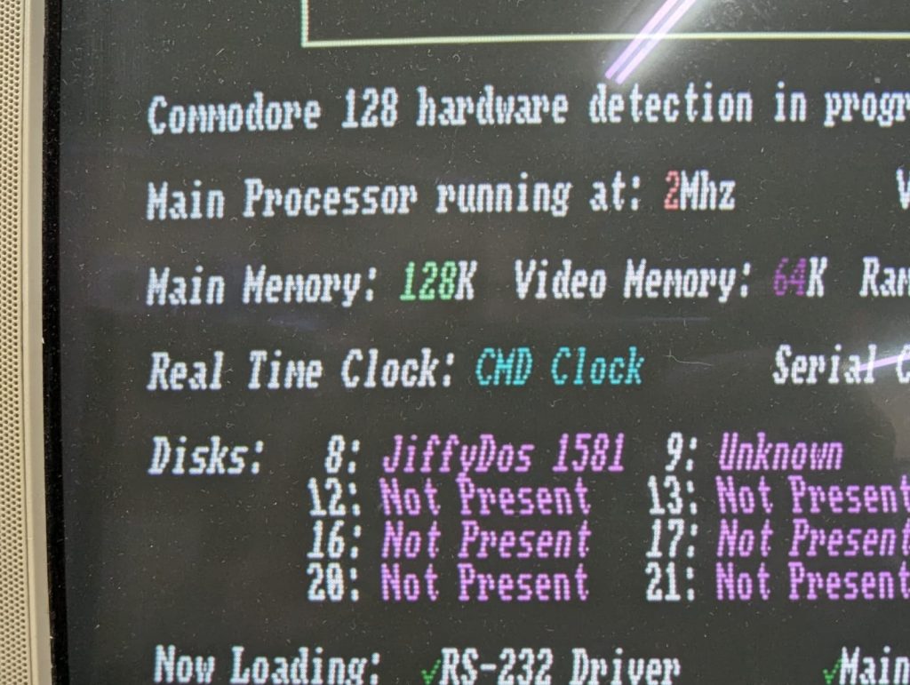
Here is DESTerm autodetecting the RTC on boot:
List of software compatible with RTC
Here’s a list of programs I’ve found that can utilize the RTC as provided by this device:
| Program | Usage | Notes |
| GEOS | Shows current date and time in the top left corner | Needs CMDTime to set the time on boot |
| DESTerm 3.02 | Shows current time on status bar | Will be auto detected at boot if available. Need to go to User settings and change the display timer. |
