A few months ago when modding my CRT I learned, thanks to this reddit thread, about the G1 mod. G1 is one of the terminals that control the pictures of a CRT.
You may be more familiar with G2 (aka SCREEN) and G3 (aka FOCUS). But G1 is usually disabled in all consumer CRTs, by tying the pin, which is present in pretty much all picture tubes, to GND. This is done because of several reasons. First, G1 needs a negative voltage, so there is extra cost by adding it. But most important, it’s because G1 makes the image too sharp.
Sharpness is good, of course, but too much of it can be annoying. In the case of television, would you rather see a flat color, or the scanlines across it? For a movie, the scanlines are certainly a distraction. But for computers and video games? We welcome them. We embrace them.
The G1 mod
The G1 mod was developed by LukeEvansSimon and published to Shmups and this post is based on DaveAstur and DreamCRT’s, guide published in this PDF. The mod is very simple in theory. It’s just a negative voltage supply, taking AC pulses from the flyback transformer, and rectifying them.
Since it’s only a biasing voltage, it doesn’t really require much current. In fact, the voltage is supplied through a 100K potentiometer and a 10K resistor. Certainly only a few microamperes are passing through.
Let’s build it
So first we need to gather the components. I decided to build this out of junk I had laying around. Old electronic boards are great sources of components, often unusual ones.
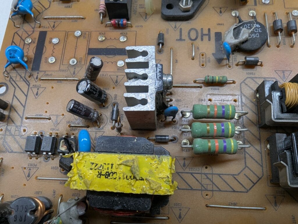
Let’s start with this TV power supply. Notice the blown SMPS controller ic. But there are a couple of diodes. When removing them, they turned out to be ideal. They were “fast” diodes which is what we need for this application.
We also need an inductor. This is probably for a low-pass filter. In the same SMPS there was this inductor, so let’s measure it
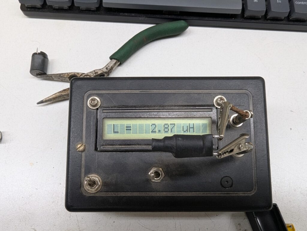
Clearly, it’s not going to work. So let’s reuse the core and wind our own.
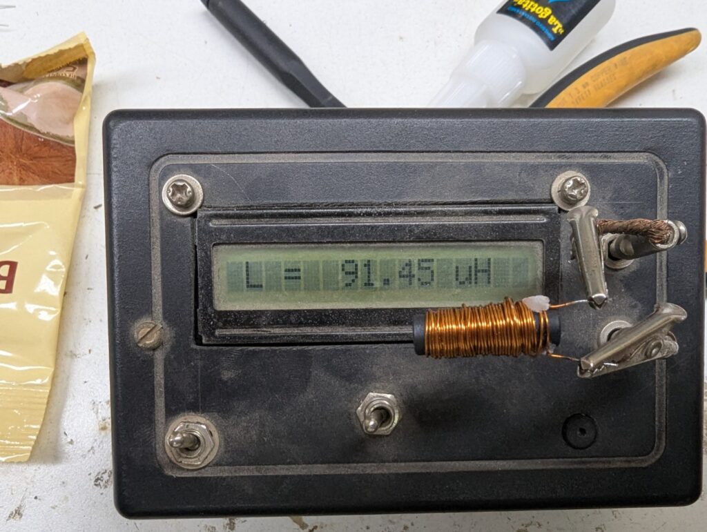
After a few turns of random enamel wire I had laying around I was able to get 90uH out of it. Close enough for our application.
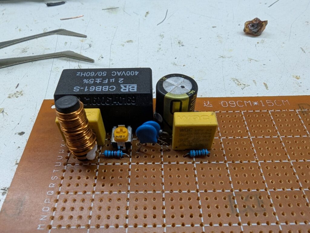
And here is the completed board. The yellow capacitors are also from that same power supply (input filters). The blue caps are new from my parts box (I didn’t have a 1000pF one so I just put two 470pF in parallel. I don’t even think they’re important). The big electrolytic is from a laptop charger, and the black 2uF one (circuit said 1uF but it’s really not critical) is from a ceiling fan speed controller.
Installing it
We need to find out how to install it. The PDF guide suggests using a scope to find the right pin where we can tap the voltage. I have something even better: the data sheet for the Flyback transformer. This TV has an HR 7788, aka 1142.5020
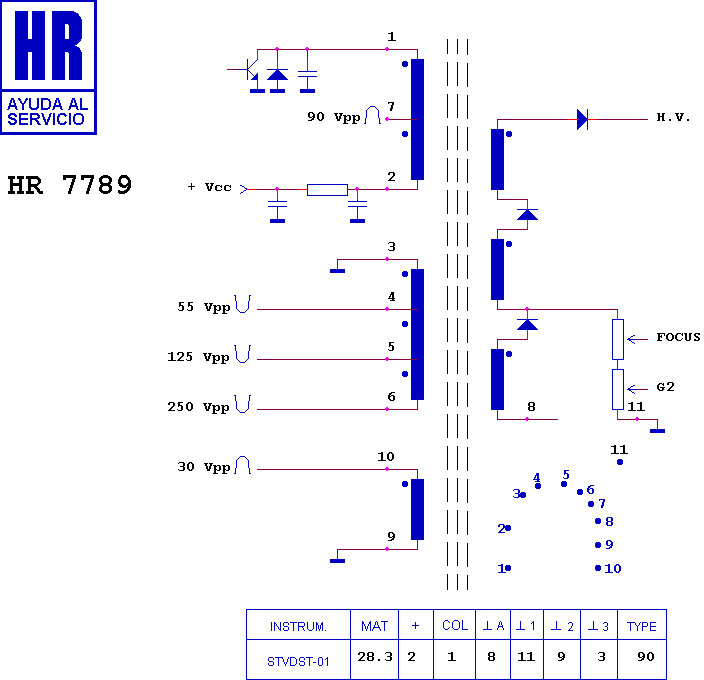
As we can see, pin 3 is GND and pin 6 is negative-going 250V. This is what we want. So let’s connect our board to it:
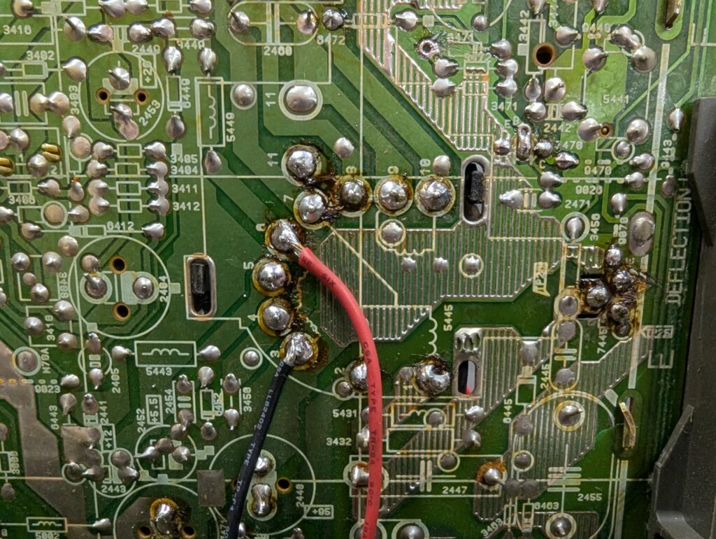
I should probably hot-glue those cables. Anyways, after measuring, I got a nice -180V out of it. Not bad. More than enough for our needs. Next, we need to solder the negative voltage to the neckboard, to the G1 pin. Sony CRTs usually have G1 labeled as such, but this Philips doesn’t. Luckily, the manual shows us the location of G1 at pin 6:
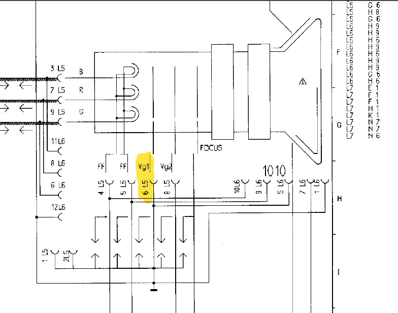
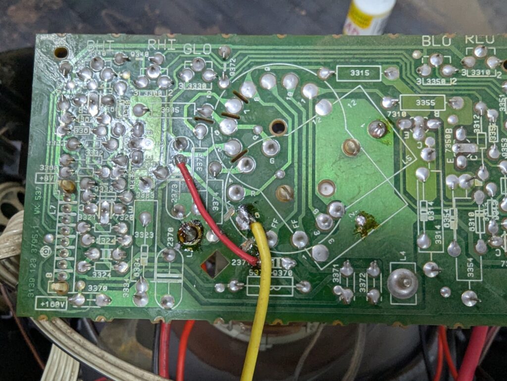
In the schematic, G1 is connected to ground as expected. G1 was in the middle of a track so I had to cut it carefully and add a patch wire. Notice the grinding marks left and below pin 6, and the red wire bridging GND. The yellow wire is our negative supply
Now we need to make sure the board won’t move around. It’s handling over 100V anyways. I made a small hole in the heatsink and mounted the board (component side touching the sink) with a screw. The capacitor prevents it from “spinning”.
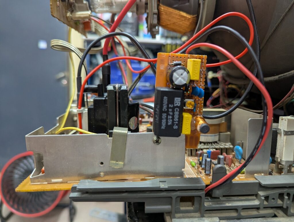
And finally we need to calibrate it. The procedure is: start with the G1 mod at in the mid position. Your picture will be completely black. But this is expected. We need to increase SCREEN to compensate. Give it a little tweak, and your image will appear. Now touch FOCUS and see if you have an improvement. Then give it more G1, then G2, then G3. At some point, the image will get worse, so go back.
The procedure is just like adjusting focus: there is a sweet spot somewhere in the middle. But usually you have only one variable: you adjust SCREEN to the right level, and FOCUS to the best position. When we introduce G1, it affects both G2 and G3 so you have three variables instead of one. It’s clear why G1 is not a thing in most consumer sets.
The results
It looks slightly sharper and has more pronounced scanlines. The effect isn’t that noticeable (maybe I need to tune it even more)
I can’t really show you how it looks. This isn’t much of a “trust me bro”, but rather, a limitation of capturing CRT images with a camera. Let’s do a 1:1 crop of the image:
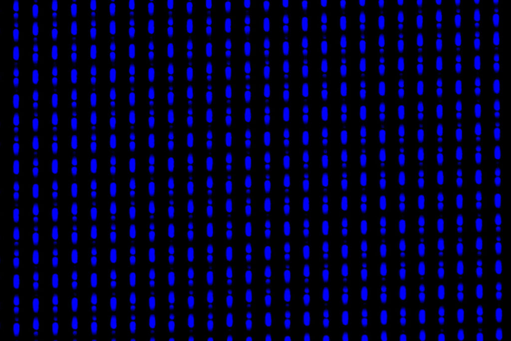
Notice the horizontal black lines. These are the scanlines.
But we don’t see images so close so let’s go back a little
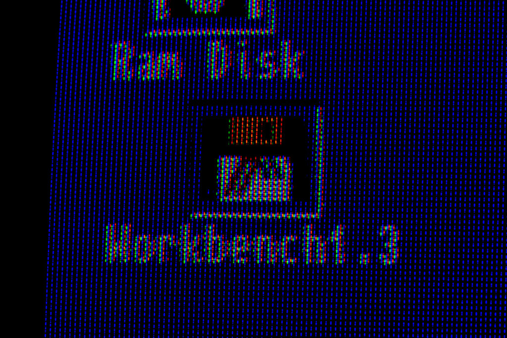
It’s really hard to capture on camera. Or maybe I need to adjust it even more to get sharper lines… or more realistically, it’s not really noticeable on a 14″ screen after all.
3 replies on “G1 mod for a Philips CRT”
You would need to use tbe TVL test pattern before and after to see if the line count changes. If it does. It then this mod just makes scanlines sharper.
The mod was not creates by DaveAstur and DreamCRT. They created a guide for the mod. The mod was created by Luke Simon in this 2020 Shmups thread:
https://shmups.system11.org/viewtopic.php?t=67124&sid=b5c3ca7f4a1992de8ac4c2da503f791f
I’ve updated the contents of the post accordingly