
While nowadays it’s very easy to connect to the many BBSs available over the internet through TELNET, there is always a way to make it more fun (or complicated, depends on who you ask).
In this article we’ll discuss the ways to connect a Commodore 64, from easiest to most complex.
The easy way
The easiest way is, actually, with a real C64 and a modem cartridge. For the modem you can use free alternatives such as the FOSS Zimodem or commercial alternatives such as the 1541Ultimate. Just connect your cartridge to wifi or ethernet, fire up a terminal app, and ATDT your bbs of choice. You’ll be online in no time (well, after you figure out how to set up your modem, if it’s userport or Swiftlink etc. But that’s part of the charm).
The second easiest way (but free!) is to use the VICE emulator and tcpser. It’s a bit fiddly to configure but once it’s set up, it’s as good as the real thing.
But we can complicate it even further.
Adding unnecessary complexity
If you have a serial port cartridge for your C64, why not use that instead? The way to do it is almost as simple as VICE+tcpser, except you need a null-modem cable. Worry not, as the pinout for this cable is in the tcpser documentation. If you choose this path, what you need to do is just run tcpser in your PC, and connect your null-modem cable. Now you can ATDT in your terminal and connect to BBSs using your PC as a “modem”.
But what if you wanted to hear the sweet sounds of dialup? Unfortunately, it’s not as simple as connecting two modems back to back and dialing each other (well, actually, yes if you use two high end modems such as the USR Courier. But the game here is to make it more complex, not easy).
A primer on analog phone lines
Phones are very simple devices really. They were invented over 150 years ago. And the way a modern (analog) phone works is essentially the same. The phone line provides a DC voltage that allows the circuit to bias its microphone, and the audio signal is superimposed on the same line. The remote end simply listens for this audio signals.
The simplest phone line you can build is two phones connected to each other with a pair of wires, and a 9V battery connected to these wires. While the line specifications call for 40 or 48V DC, when the phone is “off hook”, the voltage will drop. Phones are happy with 9V.
You can use this to connect two modems back to back. Simply issue ATD on one modem, and ATA on the other modem they will connect and act as if they were a very long serial cable.
But to actually establish connections on demand you need a little more. The most complicated part is getting a “ring” signal. But again, phones, being simple devices, are simple to ring too. All you need for this to happen is superimpose a 90V 20Hz AC signal on top of the 48V DC. This will make the “ringer” on the other end, well, ring.
Using an analog PBX
You can find those for dirt cheap nowadays. Many businesses have been ditching them for the last 20 years while migrating to VoIP. And they have everything you need to make your modems talk to each other.
Simply connect modems to analog extensions, and call them. Put one modem in auto answer modem (ATS0=1), and dial the extension with the other, using ATDTn. The PBX will ring, the remote modem and it’ll pick up.
An alternative is to use a VoIP adapter such as the Linksys PAP2 which can connect two phones. I’m not sure if you can configure it internally to do this or if you need a SIP server like Asterisk, but basically you need to be able to call one of the ports from the other. It’s important that you use the G.711 codec for this as it will provide uncompressed audio. Other codecs won’t be able to pass through modem data.
But this all still seemed too simple
Building our own, custom phone line
While the concept of a phone line is simple, the actual implementation is a bit more involved. We need several things:
- Line biasing
- Off-hook detection
- Dial tone
- Dialed number detection
- Ring generation
- Caller ID
- Connection
Biasing & Off-hook detection
Lucky for us, line biasing is a very simple business. For our purpose, a phone is a 180 ohm resistor. When the phone is on-hook, the line should float at around 48V (it’s actually -48V but…whatever). When the phone goes off-hook, this condition is detected by the CO (central office) as a 20mA DC current on the line. So in practice this means that:
- The line may be able to go lower than 48V while on hook
- As long as the phone draws 20mA we’re fine
- To detect the off-hook condition we just need to monitor the line for 0-ish mA/20mA.
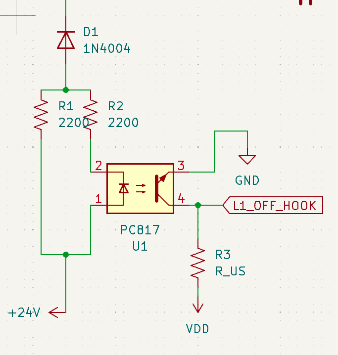
This is actually very simple to implement. We just need one resistor, and a GPIO in our microcontroller! But microcontrollers nowadays run on 3.3V. And they don’t really like being connected to very long wires either. So to make interfacing easier, we can use an optocoupler.
In the on-hook state, no current flows through the LED inside the opto. In off-hook, the phone is being biased through the LED. This will trigger the optocoupler output, and allow our mini CO to detect the off-hook state.
Dial tone
Dial tone is for us humans to hear. There are many kinds of dial tones around the world. America uses a “complex” two-tone system that sounds very nice, europe and japan use just a sine wave.
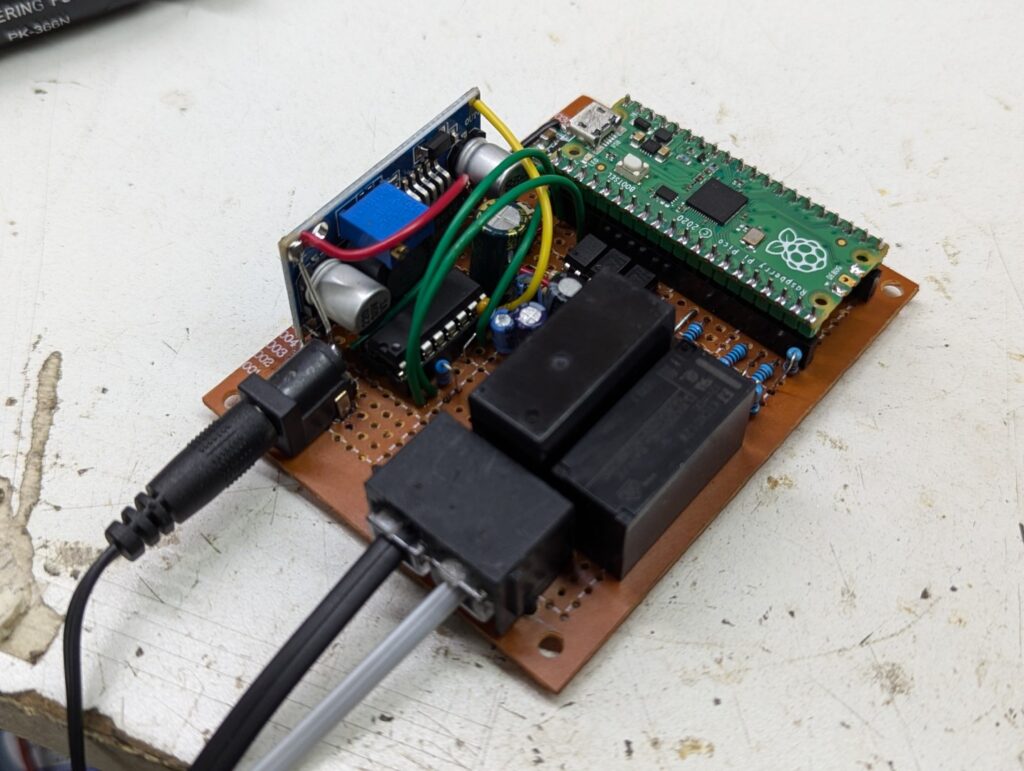
We’re using a Raspberry Pi Pico for this project. and one thing this little device has, is more than enough resources for this. We’ll be using the PWM controller, a DMA channel, and a GPIO. And a little RC filter at the output, to smooth it all out!.
For my CO, i decided to go with a UK tone. It’s a 350+450hz sine wave signal. I precalculated all of the samples in Google Sheets. Available here.
So I simply used two columns. One for 350Hz and the other for 450Hz, and the dial tone is the sum of half of each. The tricky part is finding a point where both sines will cross zero at the same time. But they need to be in the same half-cycle, and going in the same direction. That is, if we’re using a sine function, both will start at 0 and go up, hit 1, and start going down, cross zero, go down, hit -1, and start going up. We need both waves to be 1) in the negative region and 2) going up, and 3) for both, the next value should be zero.
This is easy to visualize in a chart, but a bit hard to calculate. So what i did was exploit the sample rate. We’re used to a 44100 sample rate for historic reasons, but nothing prevents us from using any arbitrary rate. It’s our system and we don’t need to be compatible with anything. So what I did was use the Least Common Multiple of 350 and 450. It happens to be 3150. So I used 31500 as my sampling rate so the filter would be easier to make. Using this sample rate and looking at the numbers closely in the spreadsheet, you can find the right cutoff point for your samples by looking at the numbers from each frequency. start from zero, and keep going down until you find a zero, where the A and B frequencies were also negative in the sample before. This will give you the perfect loop.
Dialed number detection
In the early days of telephony there wasn’t any of this. The ringer signal was literally an alternator on your phone. You cranked this and it flashed a light on the operator’s board. She (because it was considered a women’s job) would use her phone to connect to your line, ask who you wanted to call, and use a short cable (a patch cable) to patch you through to your destination. Or tell you the line is busy by just looking at the destination and seeing there is another patch cable plugged in.
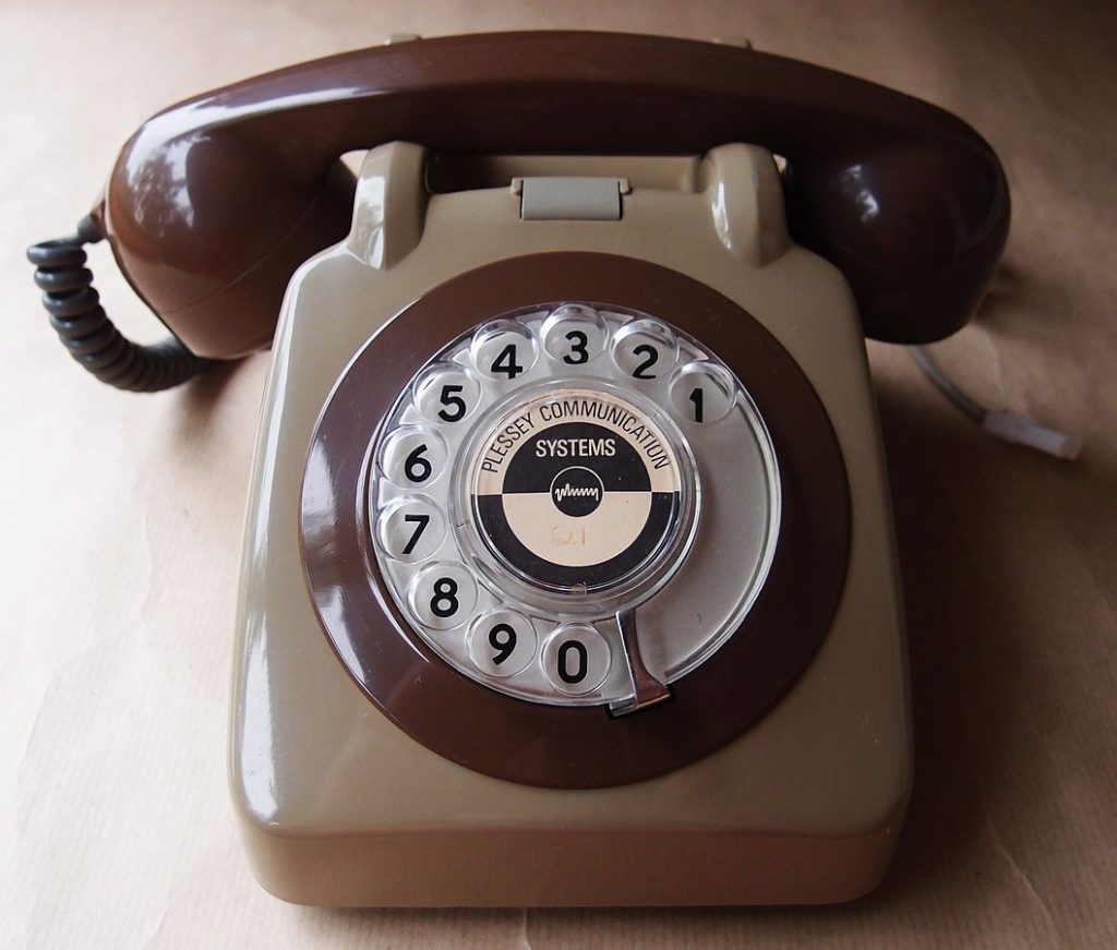
Over time this was automated. Phones got a rotary dial. This was a device that would make the line go on and off hook relatively quickly (in fact, you could do this by hand by tapping on the hook at the right pace). This, along with some clever relay logic and rotary switches, allowed the central office to automatically connect you to your destination.
In the 70s, Touch-Tone was invented. It was a way of dialing using a method called DTMF. This consists of two superimposed frequencies. The CO will detect which button is being pressed because two distinct tones are being transmited at the same time. This allows a digital CO to detect the dialed number (and it’s also much faster to dial).
Lucky for us, the Pi Pico also includes a decent ADC, and a lot of CPU power to run the Goertzel Algorithm, which will allow us to detect said tones. We just need to capture a few milliseconds of audio from the line, and run Goertzel for each frequency of interest. Then we sort the results by score, and pick the top two. After this, we look up which number corresponds to this pair of frequencies.
This was actually easier said than done. In the end, I had to implement some statistic filtering (to detect silence), and sample the line several times, and pick the top candidates using a majority algorithm to make it reliable enough.
Ring generation
Ring generation is easier said than done. In fact, many modern devices can’t generate a proper ring tone. In the past, PBXs used transformers that could generate a decent 90V but this is actually a hard problem when using low voltage power supplies. If all you have is a 12V adapter, it’s actually hard (read: exensive) to get 90V out of it with a boost converter. Most boost converters out there max out at 30-ish volts, and many phones aren’t able to detect this as a ring signal. Sadly, this also happens with commercial devices, such as VoLTE adapters.
My design is no exception. It can’t ring many phones out there, but it’s good enough for modems. The first idea I had was to just try and see what would happen if I used 30V pulses from a boost converter. This didn’t work. The problem is that the phone has a capacitor inside and the 0-30-0-30-0-30V pulses just charge the capacitor.
So we clearly need a real AC source here. The solution I found was an H-bridge. This works by “flipping” positive and negative so the phone sees 30-(-30)-30-(-30)V instead. This was also enough to ring one of my phones.
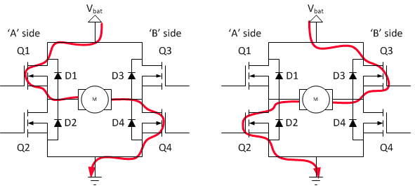
A simple and cheap L293d from ST worked great. The device is controlled from the microcontroller with 3 pins: Enable, A, and B. To ring, A and B are alternated 20 times per second, generating a +35/-35V pulse, enough to be detected as a ring.
The only problem with this approach is that the line needs to be floating. We can’t reference it to GND, otherwise the H-bridge won’t work (and it’ll short). This is accomplished by using a DPDT (dual-pole, double-throw) relay that “lifts” the called line and connects it straight to the H-bridge.
We also need to detect the line going off-hook while the ringer is ringing. This is accomplished by using a third optocoupler circuit.
Caller ID generation
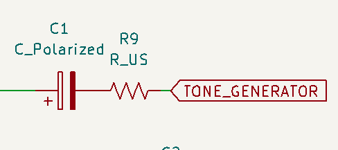
Caller ID is a very simple affair. After the first ring, and before the second one, a specific packet of data is injected into the line. It should be a Bell-202 (1200bps) packet indicating type, date, time, and calling number. The details are here. It works the same as the dialtone generation: it simply sends the GPIO signal through a RC filter for the line to receive. It’s not an ideal solution as modems would expect a more precise sine-wave but they seem to work fine. There are dedicated ICs that can generate the right signals, but this seems good enough, at least for my modem.
The caller ID, in my case, is used by the receiving software, to connect to a specific BBS. On my Commodore, if I dial “32” (ATDT32), the CO will simulate a call from 212-555-0032. The receiving software has a directory that maps the entry 32 to a specific TELNET BBS.
Technically, what I wanted to do is called DID (Direct Inward Dialing). It’s a way to dial a phone number from the public network, and have the PBX automatically connect to the right extension. But I haven’t found any information on how DID is sent – if at all. So I’m abusing Caller ID instead.
Connection
Connecting is the easiest part! It’s just a relay that connects two lines together. There is a capacitor between them, to prevent DC from flowing from one line to another (this would prevent off-hook detection once the call is established).
The firmware for this project can be found here.
The software
There was no software that could do what I wanted. There were some things that got close to what I wanted, but I had to modify them further. tcpser sounded like it was what I needed, but it wasn’t. In the end i found that sexpots was more in line with what I wanted to do.
I created my own fork of sbbs to customize sexpots.
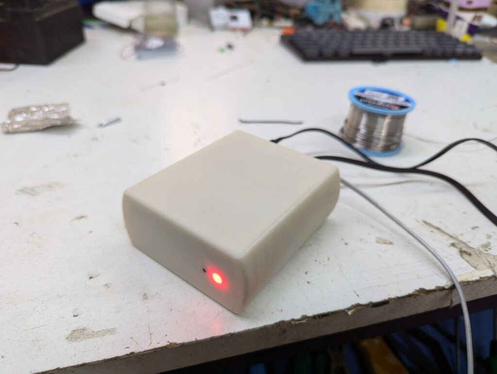
Demo
Here’s a video showing a connection from a C64, via modem, to a Linux machine, to the internet, to a C64 BBS.